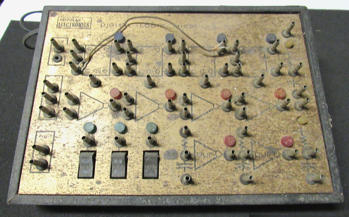
![[PE SWTPC microlab]](lab_cleaned.jpg)
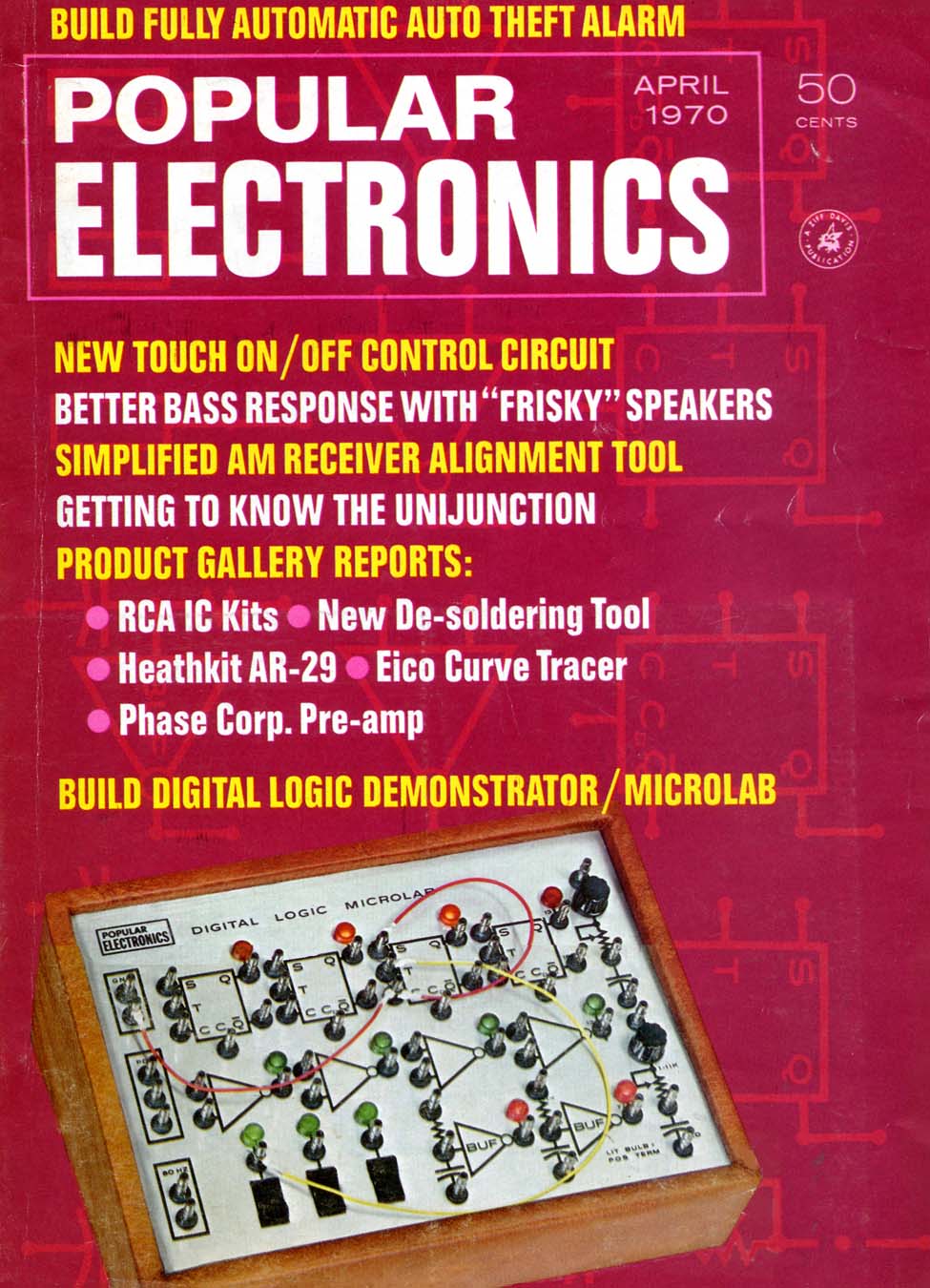
I purchased this PE MicroLab in March 2023, and did some restoration work as described here. In Oct 2025 I bought a second MicroLab, and it's also described here. These were 1970-era products of SouthWest Technical Products or SWTP, described in the April 1970 Popular Electronics magazine as a kit. I have more SWTPC products such as 6800 microcomputers as described on other Web pages.
This page was last updated Dec 1 2025 (C) Herb Johnson all rights reserved. Search my Web site to find other Web page content of interest. My home Web page for restoration of vintage computing is at this link.
This PE magazine Microlab was purchased online at auction. The price was modest likely because of its rusty appearance. But the interior was merely dusty and looked in reasonable shape.
On arrival I examined the rusty front plate. Inspection showed it was a thin steel plate with some brass/bronze coating. It was dusty and had numerous rust spots on the underlying steel. Under the plate of course, was a printed circuit board.
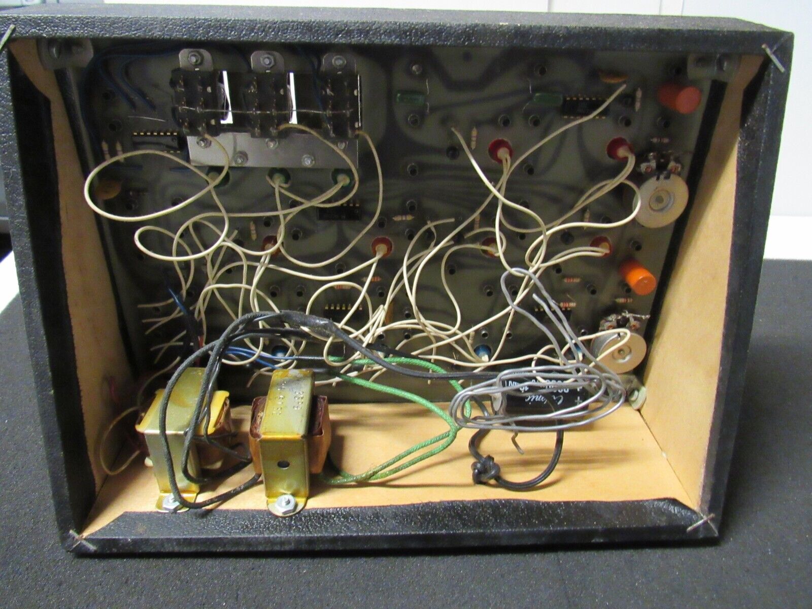
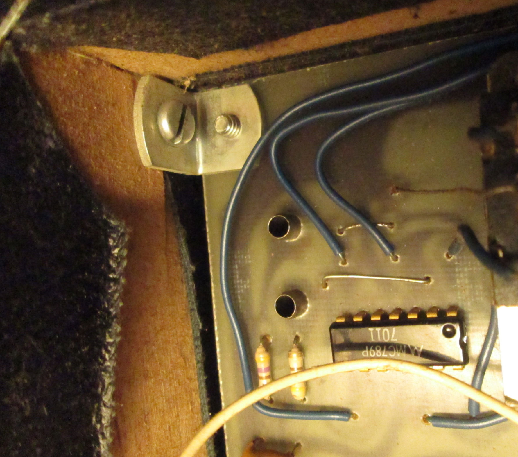
Meanwhile I inpected the case and interior. This photo of the inner corner shows many features. The case is some kind of cheap grained wood, not pressboard. Note the IC is an MC789P with datecode "7011", that is 1970 and week 11 (March). Another chip has a datecode 1970 and week 35. Those are close to the March 1970 publication date of the Popular Electronics article which introduced the product, as available from SouthWest Technical Products. This model I have, has the PE logo. Many SWTPC products of course have the STWPC logo.
The interior looked sound and in reasonable shape. Note there's no AC power switch, or AC fuse! If you look carefully at the lamps, from front and back, they were likely inserted into the front-panel before installation and then wires soldered. The PE article describes that the posts are installed on the PC board before the front panel is inserted around them. I'll consider the assembly and disassembly later.
I used a few cleaners, from Simple Green to Bar Keeper's Friend. The latter is an alkaline slightly abrasive material used with water to turn rust into crumbly iron for removal. These were not effective on the iron oxide but cleaned the brass. Inspection of the black legends on the board, suggest these were likely silkscreened black paint or ink. Most of them were intact, some probably lost to wear.
Cleaning improved the surface but there was still some residue. Some areas were hard to scrub and the brass would shine up if buffed. This photo on a cloudy day shows the overall condition. This photo in clear sunlight shows the variations in among the pegs. I don't know of a clear remedy for the exposed rusted steel.
Of course, I'll have to test and restore the power supply and confirm the condition of the logic and lamps. Probably a matter of use of a Variac to ramp up DC to the capacitors, given the light load of the circuits.
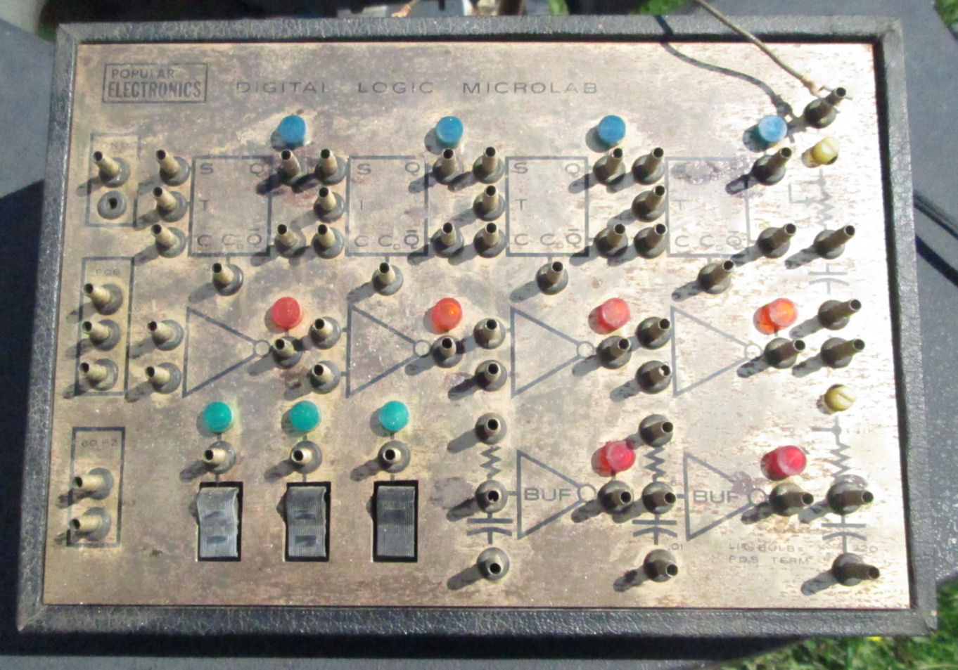
![[2025 PE SWTPC microlab]](sw_logic_clean.jpg)
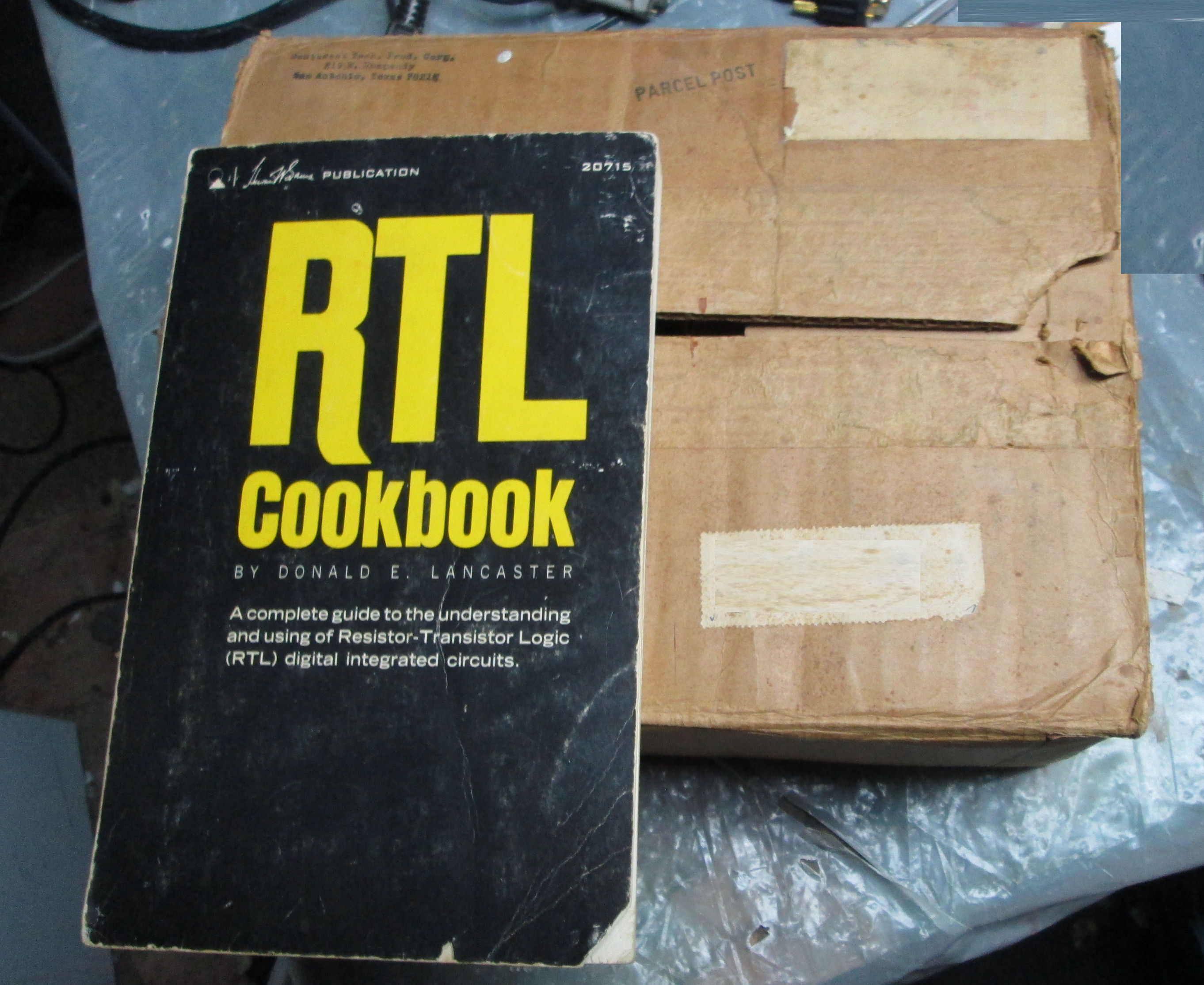
In october 2025, I obtained another Microlab, from its original owner. This one was in the box (a simple cardboard box) and came with the "RTL Cookbook" as originally sold with it, said the owner. It also had a bunch of connecting wires. In Nov 2025 I cleaned up the surface, that's the photo shown here. Cosmetically it's in better shape than my 2023 purchase.
![[2025 PE SWTPC microlab]](sw_logic_wires.jpg)
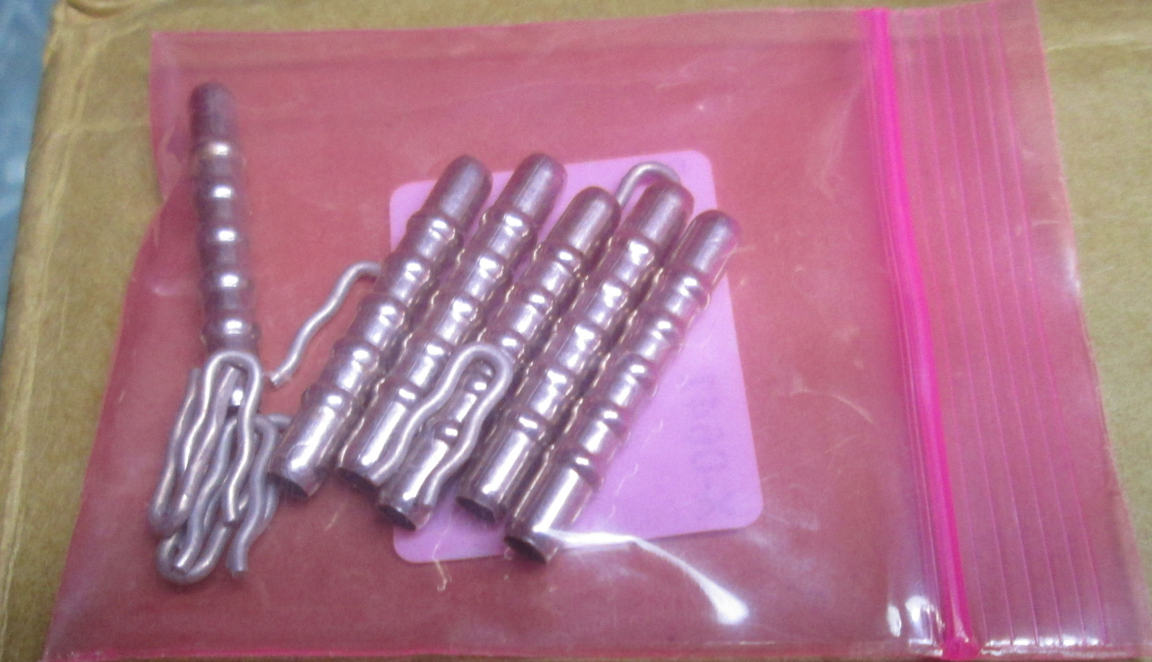
Here's the connecting wires, with the hairpin connectors. Also a baggy of unused posts and clips.
I describe the posts and clips later in this document.
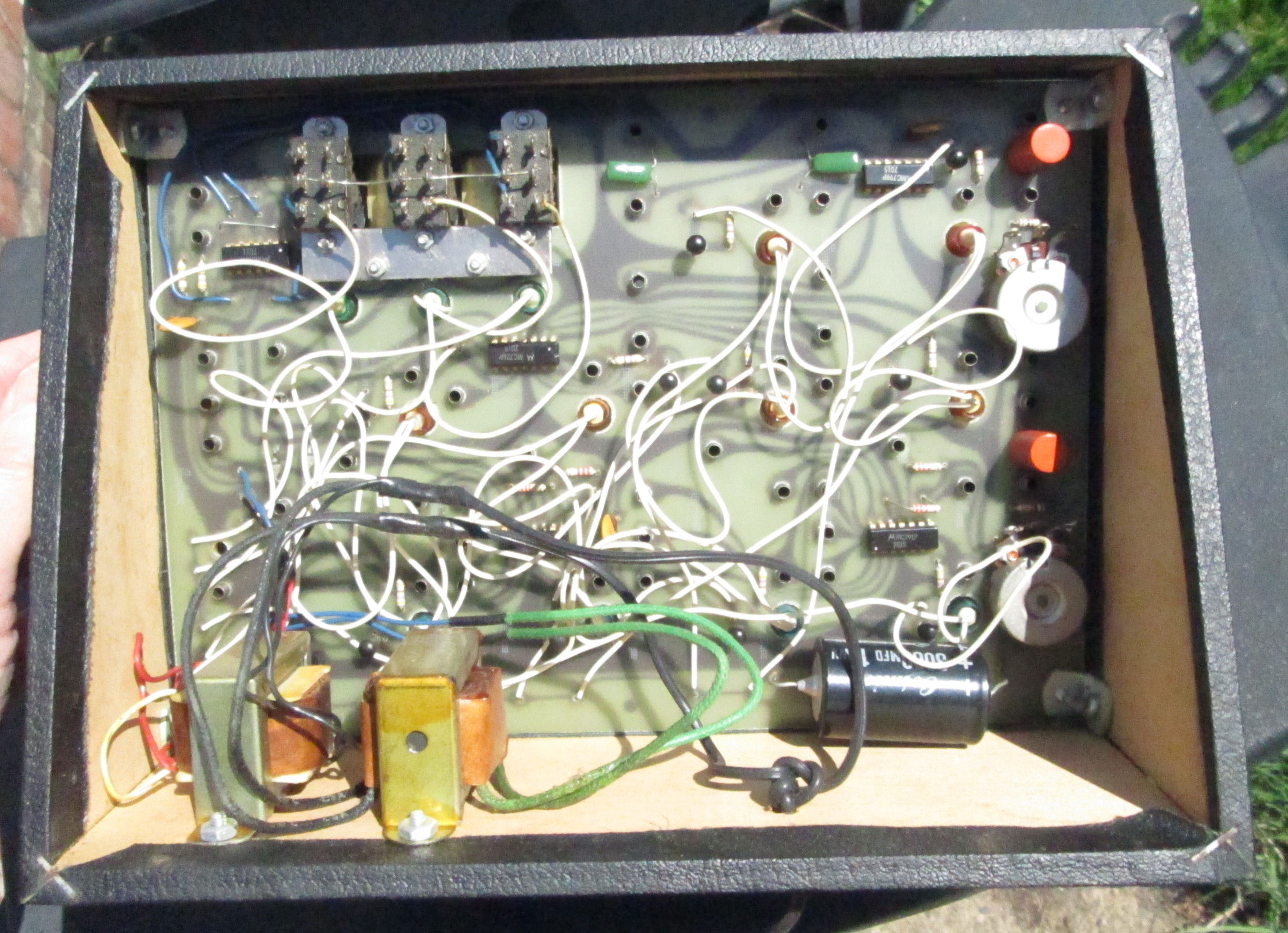
![[2025 PE SWTPC microlab]](sw_logic_interior.jpg)
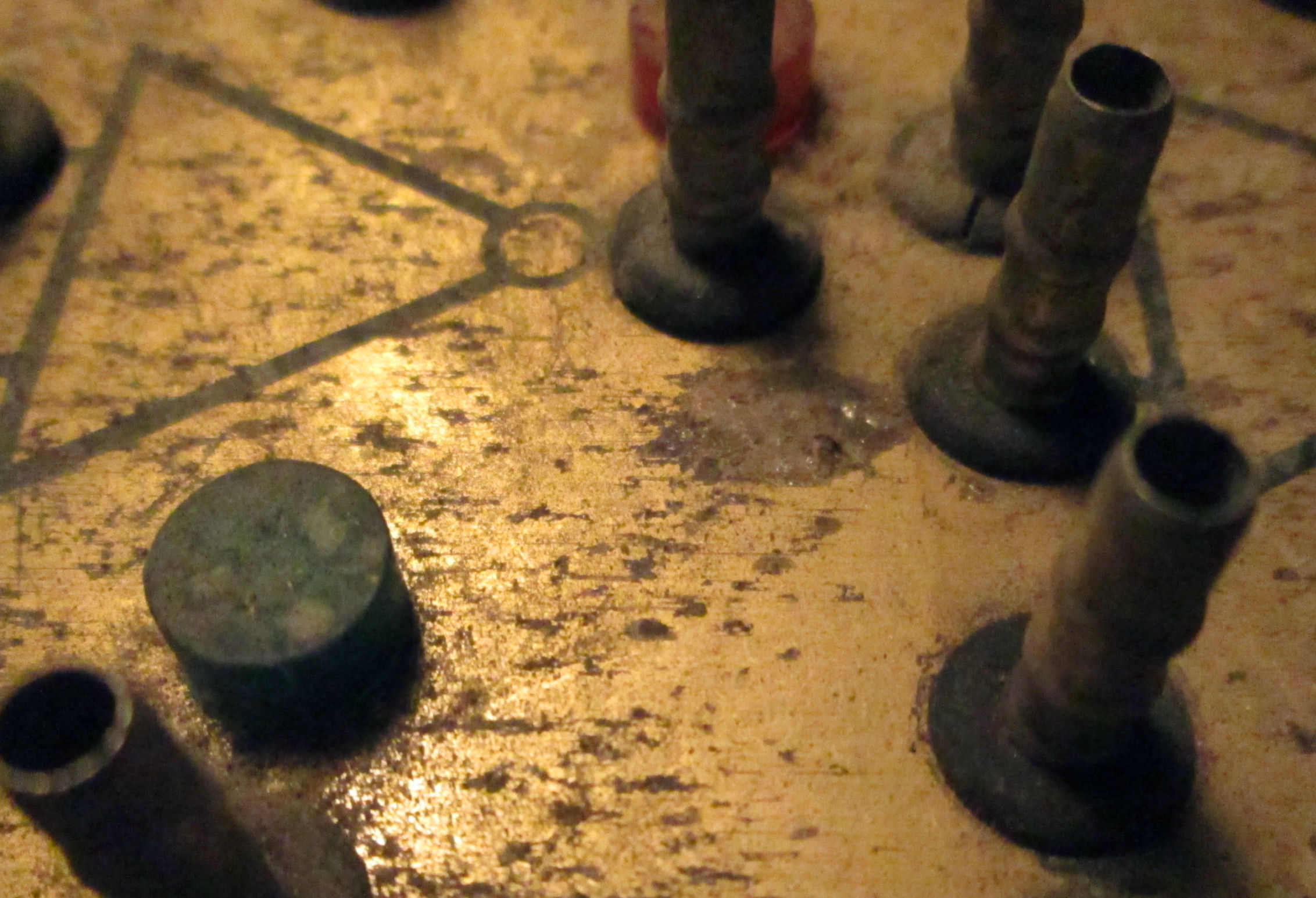
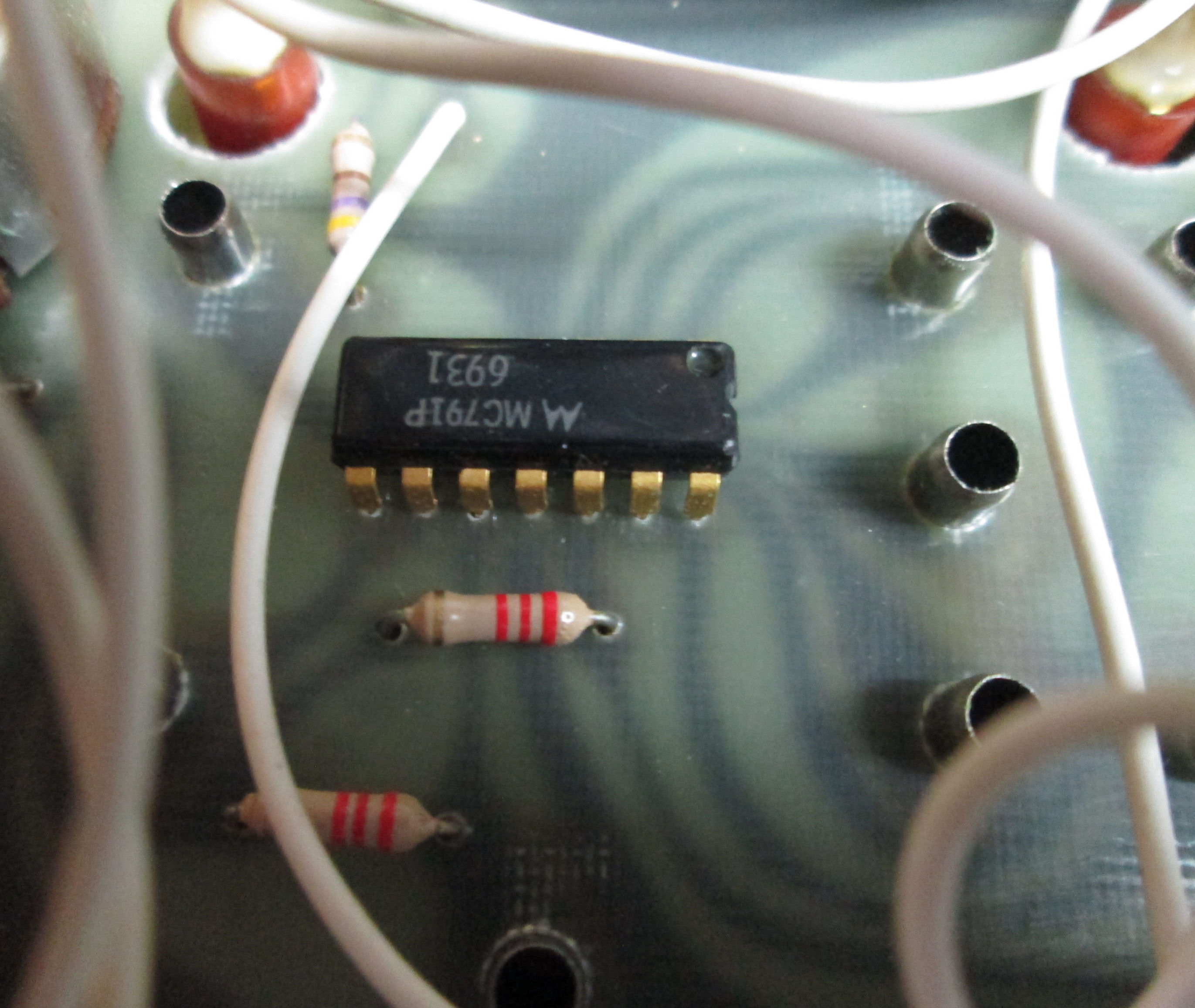
The interior looks in good shape, wired by the owner. Like my previous unit, I'll have to Variac and test. A close view
of the area around one of the RTL logic chips is informative. First, the date code is 1969 - the
kit was first offered in April 1970 so that's plausible. Note the PC board is single-sided, no traces on the component side; that
kept costs down in 1970. There's a partial view of the terminal posts. I'll take more photos in coming days. - Herb
Here's a PDF of the PE article which includes assembly and schematic and how-to-use examples.. In June 1970 there was a small correction published. The correction is the lack of logic-circuit diagrams named I, J, K. I'll check the RTL Cookbook for those, as I'll now reference.
I looked on the Web, for a SWTPC manual for the product. But the PE article refers to a "240 page experimenter lab manual" which is presumably Don Lancaster's "RTL Cookbook". Don Lancaster's Web site has a copy of his PE article, and also the RTL Cookbook. Don passed away in 2023. The article itself, has a schematic and a silkscreen image of the PC board. In the 1970's PE often published single-sided PC board layouts, for readers to photocopy and produce PC boards at-home. Often the PC boards were available from small companies, which in general from the persons who wrote the article. Don Lancaster often wrote about other companies' products, and his own publications.
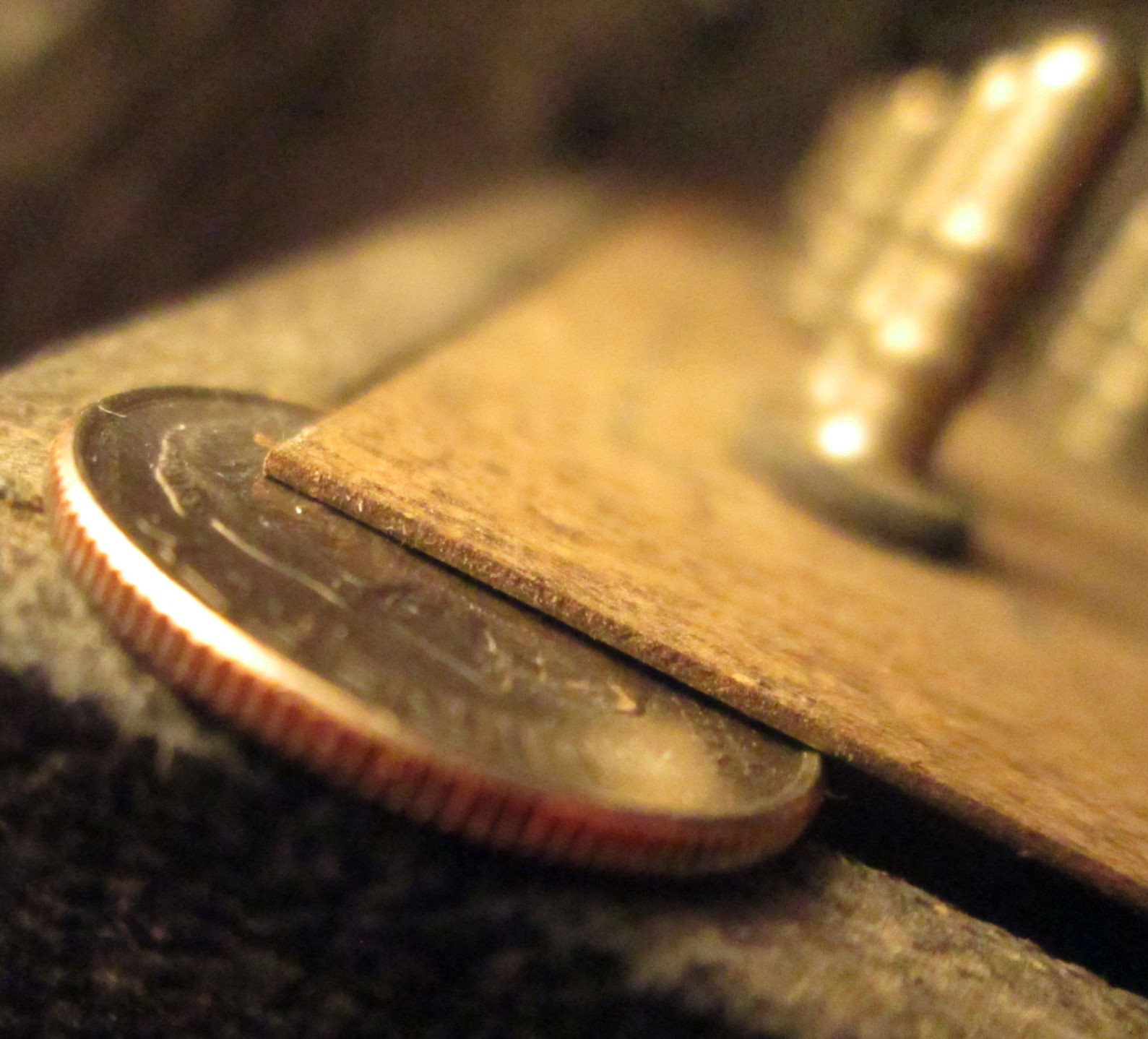
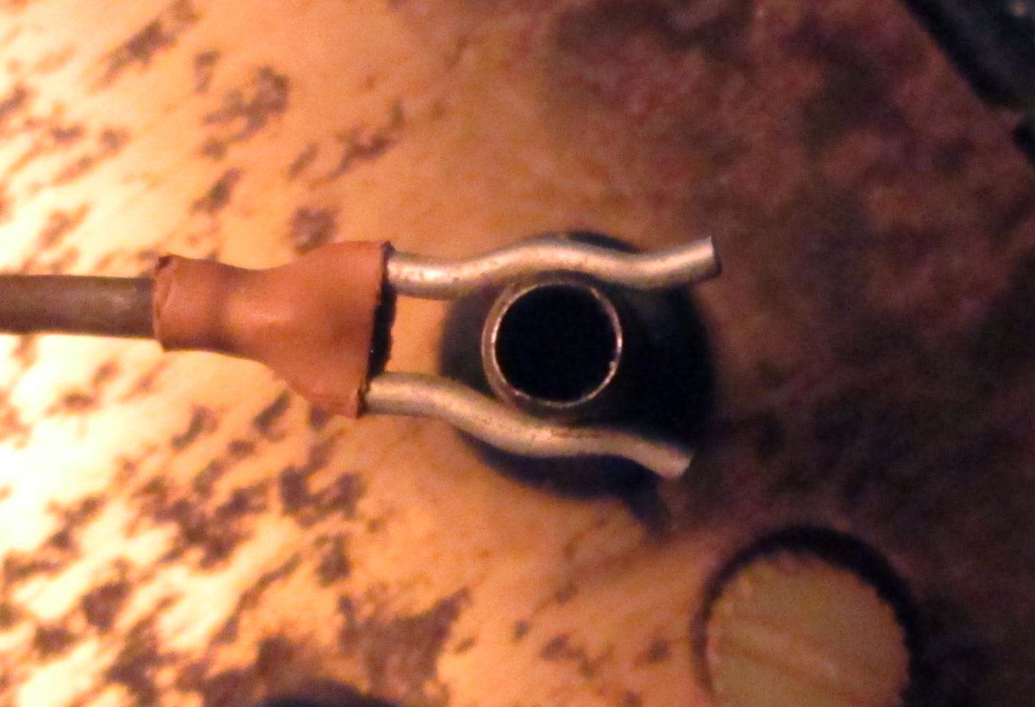
Another issue is to acquire additional wires with the proper connectors. The 2023 unit came with one wire, the 2025 unit had many wires. Here's a photo of one of the terminals and the wire connector. The PE article describes these cables as something the builder constructs. The PE article parts-list calls these "plated hair pin cotters" and "five-ferrule terminal posts", five referring to the circular bumps on the posts. A ferrule in general is a metal sleeve.
The wire connectors are called in the article, "5/32" dia plated hair pin cotters" on "#24 wire" to connect to the "terminal posts". The article says there's "unplated cotters such as GC Electronics #7378". The 5/32 fraction refers (I think) to the diameter of the circle formed by the circular arcs at the center of the hair-pin. Or it may be the diameter of the shaft-groove the pin attaches to. The actual pin is about 1/2 inch long, and the larger circle formed by the pin is close to 5/32 inch in diameter.
The wire itself is fairly thin, the article suggest #22 wires in red and yellow. The wires in the 2025 purchase are red/pink and pale yellow, perhaps faded with age.
The ferrule posts themselves are some kind of steel, which I'll need to brass-brush to clean up. The incadescent lamps are "5 volt 50mA", a description I've found in 2025 on eBay. This is a 1970 product so they aren't LED's more common by the mid-1970's.
Search in 2025 for parts vintage and modern, shows hair pin cotters like are still in production. One brand says they are "made from [either] hard drawn MB spring wire zinc plated and baked, or Stainless Steel. It will take time and attention, to select plausible parts and build wires by soldering these cotters onto wires with heatshrink to cover and anchor the join.
- Herb Johnson
Copyright © 2025 Herb Johnson